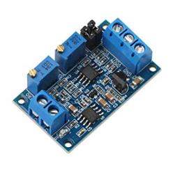
Description:
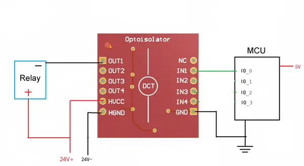
1. Function: Use the low level to control the high level. Such as the use of single-chip 3V or 5V voltage control 9V or 12v voltage.
2. HVCC should not exceed 24V. Output OUT1 / OUT2 / OUT3 / OUT4 output current equal to HVCC / 5.1K, absorption current 500ma.
3. This module uses TLP281 chip (for Toshiba).
4. Schematic:

Input and output instructions:
Input: IN1 / IN2 / IN3 / IN4, then the microcontroller or Arduino IO port, GND and the Arduino development board connected to the GND.
IN1 / IN2 / IN3 / IN4 controls OUT1 / OUT2 / OUT3 / OUT4, respectively.
Output: OUT1 / OUT2 / OUT3 / OUT4
Output: HVCC: Connect the controlled high voltage positive, HGND connected to the controlled high voltage negative
Use: When IN1 is high, the corresponding OUT1 voltage is equal to HVCC, when IN1 is low, the OUT1 voltage is equal to HGND

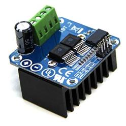
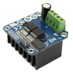
Use examples
The following example shows how to use the microcontroller's IO port to control the 24V motor rotation. Figure motor operating voltage of 24V,
red "+" that the motor power positive, black "-" that the motor power supply negative. When the microcontroller IO_0 output high, the motor rotate,
when the IO_0 port output low, the motor stops rotating.


 Paiement: Tous les types de paiement disponibles
 Livraison: Option de mode de livraison diversifiée
 Politique retours Echange ou remboursement possible sous conditions